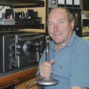
David Macnaughton and his Fascinating World of Amateur Radio
A RECEIVER EVOLVES - THE 7MHz TUNEABLE IF
CONTENTS
Please Scroll (16 items)
![]()
![]()
![]()
![]()
![]()
![]()
![]()
![]()
![]()
![]()
![]()
![]()
![]()
![]()
![]()
![]()
![]()
![]()
![]()
| A Receiver Evolves My New 7MHz Valve Receiver (mainly for AM work) Click image to view full size
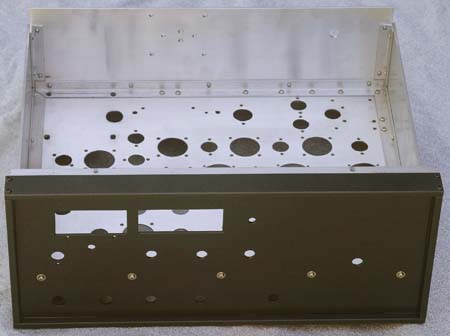
27 March 2006 The chassis has been punched and drilled, but no components have been mounted
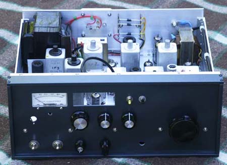
8th April 2006 The receiver still has work to be done, particularly in the front-end which is not tracking well. I have left this section until the last. However, most sections are working and quite satisfactory. You will note a large hole in the panel and this is for the digital counter dial which is under construction at present.
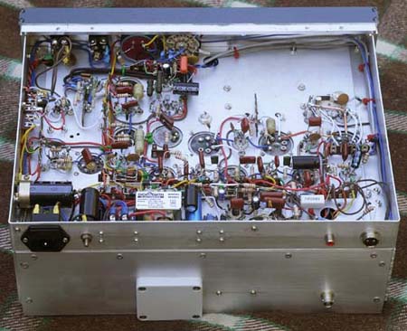
22nd April 2006 Almost completed. Receiver is running smoothly and has been used on air. All front panel facilities have been wired in and most of the inevitable bugs have been eliminated. The box underneath the chassis houses the 6CB6 RF amplifier, and a shield separates the grid circuit from the plate circuit. This box eliminated an oscillating front-end and it was one of those no win situations. If you put it in it would take a lot of time and effort and it possibly would never have been needed, but if you don't put it in you would end up with a cranky front end. So I had to make it and "implant" into the rest of the wiring. Some of the wiring still has to be cleaned up etc. Does anyone have any idea where I can buy white Decals to put on some lettering? There used to be a product called (I think - it was 40 years ago!) "Teknicals". It even came with a solvent that dissolved the clear plastic backing and just left the letters embossed on the panel. A BRIEF DESCRIPTION OF THE RECEIVER * Tubes: 16 2 x 6AM5 - Audio output push pull 2 x 12AT7 - Audio amp and phase splitter - BFO & BFO buffer 1 x 6J5 - S meter driver (Yes! an old metal 6J5 from WW2) 3 x 6AK5 - 1500 KHz amplifier and wave shaper - Modified Infinite Impedance Detector (see "Why did my receiver have distortion?" below) - Audio amplifier 4 x 9003 - IF amplifiers - RF amplifier 2 x 6BE6 - Product detector for SSB - Converter 1415KHz IF to 85KHz IF 1 x 6BA7 - HF pentagrid mixer 1 x E180F or 6688 - HF conversion oscillator * Bands: Just one - 7MHz. * Dual conversion - uses old Command Receiver IF's. (3 at 1415KHz and 2 at 85KHz). Past experience has shown that only two IF's at 85KHz are needed for excellent selectivity for AM. Three IF's cause sideband cutting and muffled sound and we don't want that! * AM & SSB * Push Pull audio output (2x 6AM5) - for that lovely clear sound that valve amplifiers can produce. (see "Why did my receiver have distortion?" below) * Tone controls: Bass & Treble - boost & cut - these controls are about the valve equivalent of Digital Signal Processing (as I see it!), but as far as I am concerned, a whole lot more useful. * No mechanical dial - uses a counter module kit to count VFO frequency then subtract the 1415kHz IF. May not be as accurate as the synthesizers used in modern solid state tranceivers, but this is not a modern solid state receiver. * Incorporates a diode noise limiter. WHY DID MY RECEIVER HAVE DISTORTION? A valve receiver can reproduce excellent sound. That is one of the reasons that I did not use solid state. However, the sound was not as I expected and I must admit that fixing it was more of a task than I had bargained for. 1. Weak 6AL5 detector. This was the easiest fault to fix. The sound was very mushy but responded well to a new tube. Still, there was distortion. Something else was wrong. 2. Over-drive of audio amplifier. The oscilloscope showed up this one. The drive into an audio stage exceeded the cathode bias voltage. A small preset potentiometer was used to preset the audio level into the stage. The sound was better but still distorted. More time needed with the oscilloscope! 3. The waveform on the plate of the same AF amplifier was very distorted. This was caused by a poor selection of resistor value for the plate load. With a HT voltage of only 170 volts, this resistor needed to reduce the plate voltage to about 85 volts so that a wide AF swing could occur, without getting to close to either limit. The value I had selected was 220K and the waveform was compressing badly on the lower swing. A change to 100K fixed that one. I was getting depressed - I still had distortion! 4. How often do you hear of hotting up front-ends? Why use a low gain tube when there are plenty of higher gain tubes available and after all, why not use the hottest that is available? This next distortion producer was found unexpectedly. The tube I had selected for the project was a 6CB6 - a TV IF amplifier. I was fiddling with the front-end and had plugged in a 6AH6 - a tube with higher gain again. The result was higher S meter readings and MORE DISTORTION. I plugged in a 6AK5 and although it had lower gain than the 6CB6, the receiver sounded much better. So I plugged in a low gain, remote cutoff 9003, all the way from WW2. Gone was most of my distortion. Seemed the higher gain tubes were overdriving the 6BA7 mixer and producing all manner of rubbish and distortion products. Think of this next time you think of hotting up a receiver with a "better" tube than the manufacturer had used. It may work on VHF but on a band with huge signals high front end gain is not a good idea. A good tune around 40M indicated that SSB sounded great, but AM was still a bit rough especially on the strong commercial stations. For me, I knew the receiver could work better but I was running out of options. 5. The big break-through! I must say that right from the beginning I had a doubt about using a diode detector. I knew that the infinite impedance detector had excellent performance in the distortion figures, but I wanted AGC and infinite impedance detectors don't normally provide AGC voltage. Some research into an old book by RSGB "Amateur Radio Techniques", printed in 1974 had a circuit of an infinite impedance detector that produced AGC voltage, so I took out my 6AL5 and wired up a 6AK5 as per the circuit from the book. It worked! The only problem was the production of much too much AGC voltage (about 25 volts of it!). This was easily reduced to manageable levels. Gone was my distortion. Here is the circuit of my detector as it now is:
Note: If more or less AGC voltege is required for your particular application, this can be adjusted by selecting different values for Cx and Rx. (The original circuit used Cx = 60pf and Rx = 47K. Why use a diode detector when this little circuit works so much better and will even save on heater consumption?
|


![]()