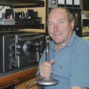
David Macnaughton and his Fascinating World of Amateur Radio
BEAM ANTENNAS AT VK2BA
CONTENTS
Please Scroll (16 items)
![]()
![]()
![]()
![]()
![]()
![]()
![]()
![]()
![]()
![]()
![]()
![]()
![]()
![]()
![]()
![]()
![]()
![]()
![]()
|
Yagi Beams at VK2BA
Antenna Dimensions And Polar Diagrams:
This section has been included because I often get asked details about my home brew antennas. I do not claim any fantastic properties or performance but they are the result of over forty years of antenna construction, are very lightweight yet robust, cheap to constuct, and you can make them yourself, and they work. To me, the internet seems to be a great way to share knowledge and techniques so I hope that you find this section to be of value. I don't consider that this page will necessarily provide sufficient information for these antennas to be duplicated, so I would suggest that you let my ideas trigger your constructional imagination and use the dimensions as a starting point for your own computer modelling. The antennas were modelled using YO 6.5 Yagi Optimizer. All three antennas shown below use similar construction methods.
All I ask is that you acknowledge this page as the source of the information if you use some of these ideas in your own article.
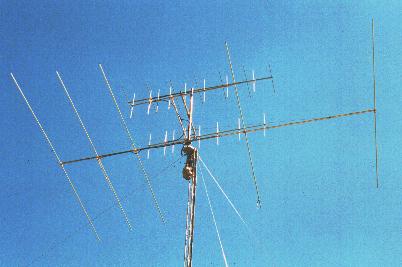
Photo 1: The Six Metre array - 7 elements on 12M (40') boom
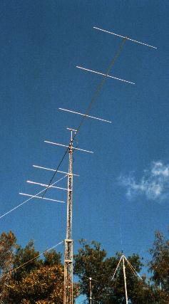
Photo 2: The old Ten Metre aray - 5 elements on 7M (23') boom This antenna was in use up to Mid April, 2000
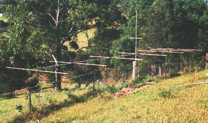
Photo 3: This is the new 29MHz, 6el yagi during construction It is now in use for 10M AM contacts. The design information for this new antenna is included in Antenna
Dimensions And Polar Diagrams:
One can make very lightweight designs that will stand the test of years. Having said that, I realise that some people have problems with ice, snow and strong winds. These lightweight designs may not stand up to such conditions. The three designs presented here use aluminium booms only 32mm (1 1/4") diameter, yet one of the 10 metre beam is 7 metres (23' 5") long, the other is 7.94 (26' 1") long, while the six metre beam is constructed on a 12 metre (40') boom. All three antennas use stainless steel bracing cables to prevent boom sag, a technique that enables the use of small diameter booms that contribute considerably to the light weight of the antennas. All antennas can be easily held and balanced by one hand and this feature is appreciated during installation on the mast. There is one final point that needs to be mentioned: I do not recommend steel or brass tubing for the boom or elements - it is too heavy. A long boom made out of steel is almost impossible to keep straight even with supporting cables. The excessive weight causes it to sag more than aluminium and the attempts to brace the sagging can cause an "S" bend to occurr. I recommend that all elements be sealed at each end with a little plug of silicone sealant to reduce the chance of a tuning fork type resonance which can in time cause the element to fracture due to metal fatigue. Another idea is to thread a length of light nylon rope through the element. This has the effect of damping down the resonance.
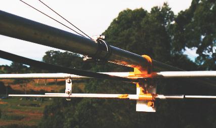
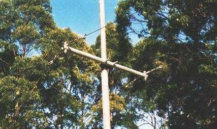
Photos 4 & 5: The Six Metre array during construction. It was assembled on the vertical 38mm (1 1/2") steel pipe that would be clamped into the rotator up in the air. Photo 6: The Six Metre driven element with the PTFE (Teflon) coaxial gamma match. This home made component was turned on a lathe and is waterproof (in that water cannot effect it), UV proof and just about the best material available for RF. Also note the sheet of 6mm (1/4") PTFE holding the gamma match assembly. PTFE is expensive material but well worth the expense. The element mounting is a "U" bolt around the boom and through two holes in the element. The block that holds the element at right angles to the boom is made of fiberglass. It is a home made device and is similar to the units used on a commercially made array. I have made a mould out of Dow Corning, two part setting, silicone rubber and I make a set of blocks each time I make an array. A length of Belden 9913 coax runs to the centre of the array where a connector enables connection to the main feeder. An application of epoxy paint over the assembly stops corrosion of metal parts and UV deterioration of the fiberglass block.
Photo 7: Another view of the gamma match assembly. Note the clamps holding the stainless steel support cables to the boom. This method of mounting means that no holes are drilled in the long boom which could cause a catastrophic failure.
Photo 8: This is the cross brace that holds the stainless steel support cables. Small stainless steel turnbuckles accurately adjust the tensions of the cables and take the sag out of the boom The turnbuckles are locked by lock nuts and remain in adjustment.
Antenna Dimensions And Polar Diagrams:
|


![]()