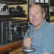
David Macnaughton and his Fascinating World of Amateur Radio
HRO 50T1 RECEIVER RESTORATION PROJECT
CONTENTS
Please Scroll (16 items)
![]()
![]()
![]()
![]()
![]()
![]()
![]()
![]()
![]()
![]()
![]()
![]()
![]()
![]()
![]()
![]()
![]()
![]()
![]()
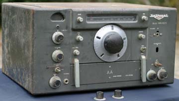
| The HRO 50T1 Receiver Restoration Project Click image to view full size Early in 2004 I received a letter from Dean, VK4ALN, generously offering me an HRO 50T1 from the early 1950's. Dean said that it had been stored in a cupboard for many years and while it was not in good condition, I was welcome to it if I intended to restore it. While it was certainly very rusty, it was decided that the best approach was not to strip it right down for a replate as had been done for the AR7, but that as much rust would be scraped off as possible and clear varnish would be applied to the chassis and of course fresh paint on the cabinet after a major sand down. It had a burnt out mains transformer and an old TV power transformer was located that had similar voltage ratings to the old one, but much higher current capabilities. It was installed. The unit had no audio output transformer, as it had burnt out too. The output was a pair of 6V6's in push pull, and so a replacement audio transformer was fitted. Next, all the resistors and most of the capacitors were replaced with new ones. Circuitry wise, the HRO 50T1 is quite curious. It is a very standard circuit for a 15 valve, single conversion receiver, but the front end consists of two stages with 6BA6's, a mixer using 6BE6 then a 6C4 as the HF oscillator. That is the end of the miniature tubes. From there it uses a 6K7 and two 6SG7s in the IF and a 6H6 detector. The BFO is a 6J7 although I found the 6K7 worked better. There is a 6SN7 as S metre driver and audio phase splitter, a 6SJ7 as an AF amplifier and then the 6V6's as push pull output. A 6H6 performs the task of adjustable noise limiter. One can only assume that National had a stock of the older octal tubes that they wanted to use up, but they used the four 7 pin miniature tubes in the front end for their improved performance. I have now removed the first 6H6 (detector stage) and in place have wired in a 6SA7 as a product detector to improve SSB performance. There was only a slight reshuffle of wires on the mode switch, and no changes to the front panel. A 7 pin tube socket has been inserted under the chassis near the old 6H6 socket and a 6AL5 has been used in place of the 6H6. I was using a pair of germanium diodes in place of the 6H6 at one stage and they worked fine, but why use solid state when one can use a tube? IMPORTANT SAFETY NOTE: If anybody ever restores a receiver of this type, please note that an asbestos gasket is fitted between the RF chassis and the Power Supply / audio output chassis probably to reduce heat transfer. This asbestos is extremely dangerous and the fibres must not be inhaled. This was one reason why I did not pull the receiver apart for replating. I sealed the asbestos with clear varnish, brushing plenty in and allowing it to set. I have recently found more asbestos in an old broadcast receiver I was restoring. A sheet measuring about 3" x 10" had been used to stop tube heat from heating up the plastic on the top of the cabinet. It was dealt with the same way with varnish. Original state
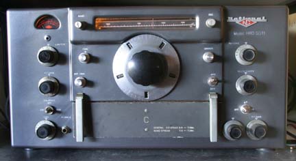
After restoration The paint on the coil box is still original at this stage. Comparing the paint colour on the coil box to that on the cabinet will give a good idea of the degree of colour match achieved. The original paint was slightly metallic and the fresh paint is more so. I will take some inside photos of the old receiver next time it is open and add them to this page |
![]()