David Macnaughton and his Fascinating World of Amateur Radio
MY NEW PROJECTS & ODD THINGS
CONTENTS
Please Scroll (16 items)
![]()
![]()
![]()
![]()
![]()
![]()
![]()
![]()
![]()
![]()
![]()
![]()
![]()
![]()
![]()
![]()
![]()
![]()
|
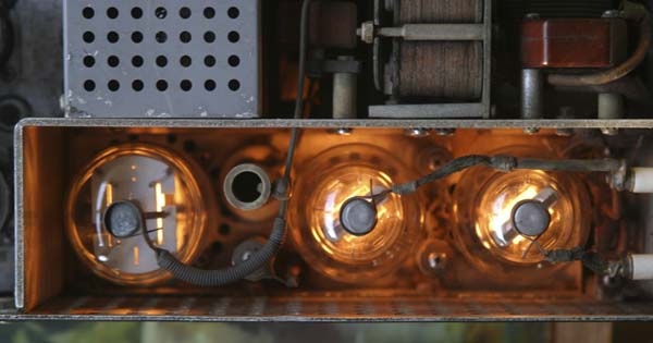
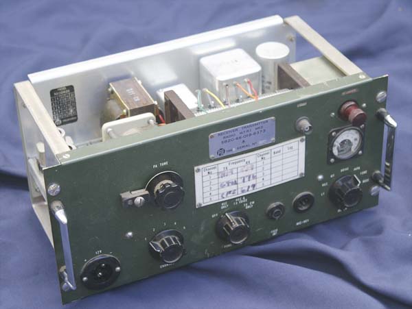
UPDATED 11th December 2010 My new ART13 WW2 aircraft transmitter. Click on image to view full size
Now, if this sight doesn't excite a valve enthusiast, then I don't know what does. When I hooked my new ART13 transmitter up to the the 28 volt supply (below) this is the view I got
The transmitter also went into a self tune mode and auto-tuned a channel that was preset prbably during the second world war. I don't know what the frequency was, but I wonder how many modern transceivers will do that in seventy years time?
|
|
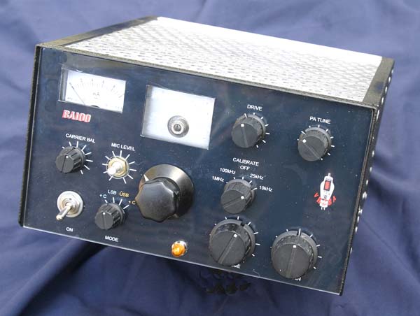
THE 40 METRE VALVE TRANSCEIVER -
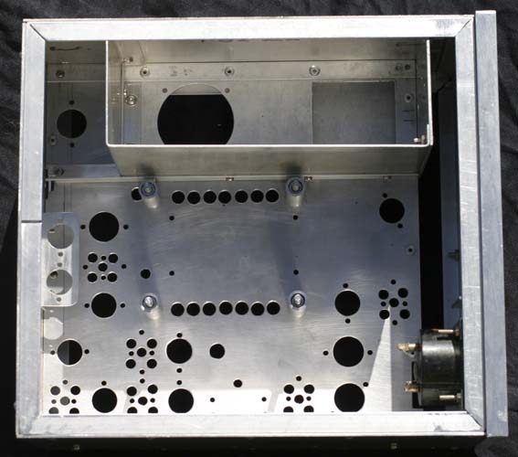
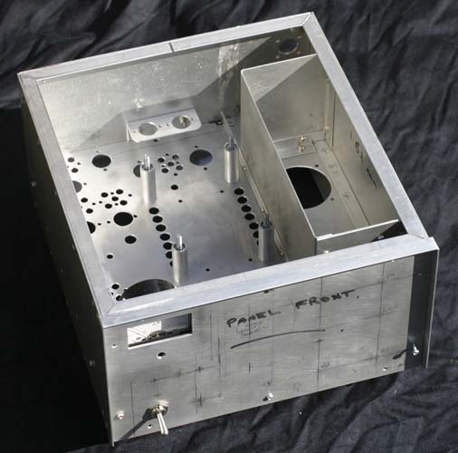
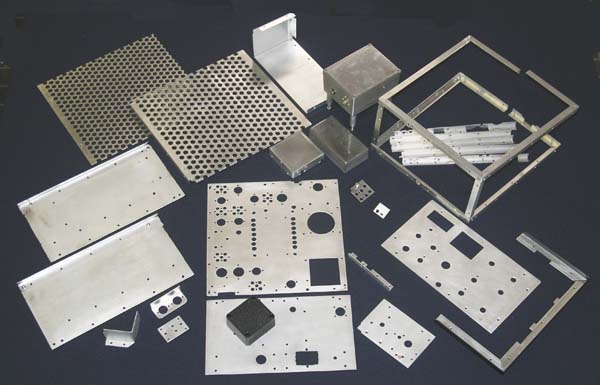
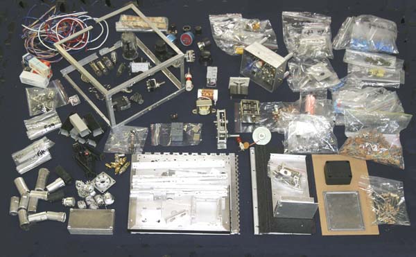
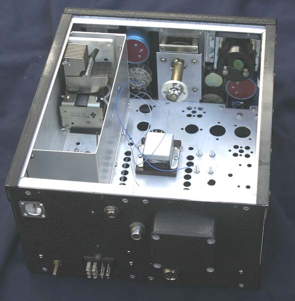
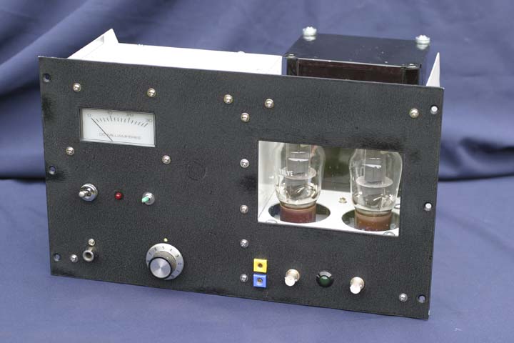
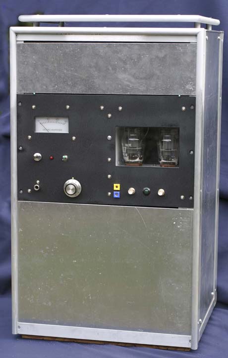
THE BA100 I was recently asked ifthis project was ever completed. The answer is not yet. The reason is that I was very ill with encepholitus in 2006 and again in 2008. This resulted in 5 weeks total in a coma and this resulted in serious hand shake. The tightness of the construction and in particular the difficulty I had soldering meant that I have put the project to bed for a period. Try soldering when the solder is shaking and you have to chase it with an iron that is probably shaking as well! This is a project that I intend to complete and I should be able to do that before too long. For those who have emailed me, thanks for the encouragement. 4th JUNE 2008: To satisfy a number of on-air requests for information about this project, here are a few early photos. The chassis is well advanced but not complete. It needs further shields then it will be totally pulled apart for a final cleanup and dipping in Caustic Soda. It is real fun putting it back together again.
15th JUNE 2008
The metalwork kit after dipping in Caustic Soda
A probable kit of bits for the project - yes, a lot of collecting went on! Now, to put them together
14th JULY 2008 Things are getting serious, folk. Just think of the possibility that it may not work!
The project is taking shape. The panel is a print-out from Photoshop and has a sheet of acrylic over the top (see below). The blemishes are reflections from the cloth. A knob still has to be found - I bought it. The top cover slides in - yes, a possible cause for TVI. I have a rescue worked out in case of this.
6th AUGUST 2008
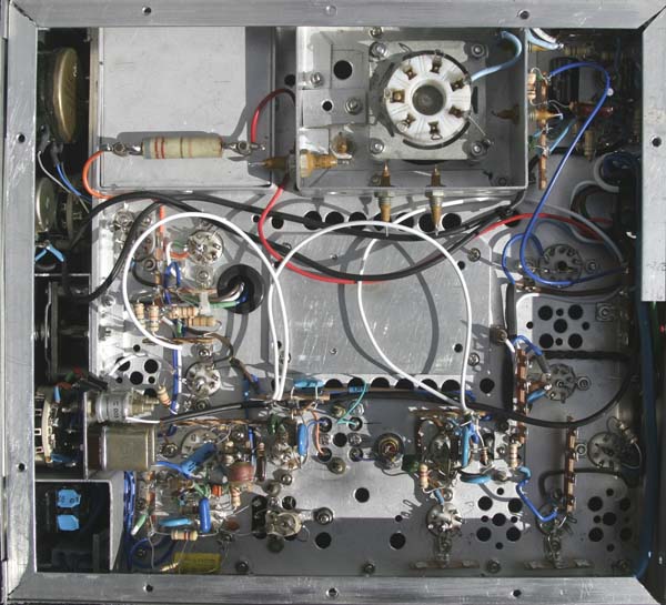
The wiring is being put in. Each section is being made to operate when is completed. So far the following sections are working: The audio output (6GW8), carrier oscillator and balanced modulator (6AR8), 9MHz carrier amplifier (6BH6), VFO amplifier (6BH6). I am having a few problems fitting in the microphone amplifier but it will fit.
The inspiration for the BA100 has been an article by John Isaacs W6PZV in the book SINGLE SIDEBAND FOR THE RADIO AMATEUR (ARRL 1970 - page 73) I am going my own way in many areas, even the valve line-up. At the moment, this is likely to be:- Receiver RF amp - 6BZ6 Speech amplifier - 12AT7 Receiver mixer - 6AK5 VFO amplifier - 6AK5 Balanced modulator - 6AR8 IF amplifiers - 6BA6 Product Detector - 6C4 Transmit mixer - 6BE6 Transmit Driver - 12BY7 RF Power O/P - QQEO6/40 (5894) type Voltage Regulators - 0A2, 0B2 Transistor regulator - MJE10012 VFO - Vackar Oscillator - MPF102 (osc) + amplifier 2x 2N2222
Filter to be used - 9MHz McCoy Silver Sentinal and matching crystals After all, I have had two of them put away since about 1968 - Now is a good time to give one of them a run More on this project soon - stay tuned
|
||

![]()
|
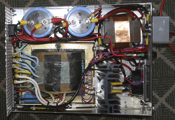
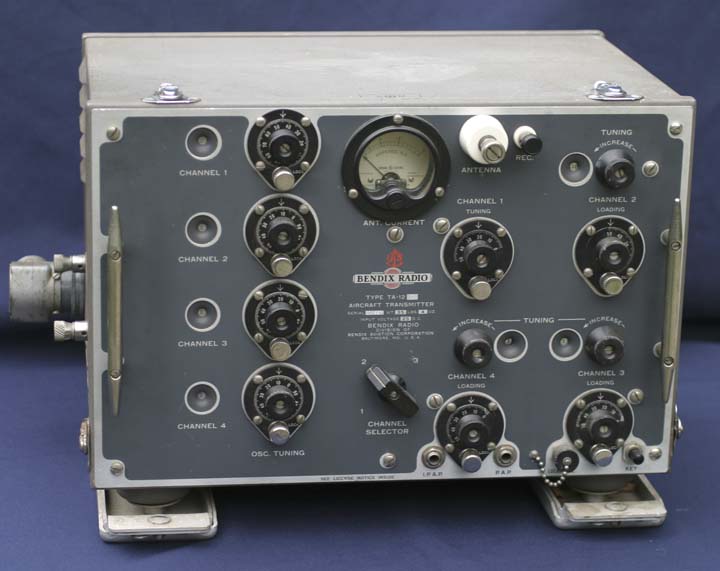
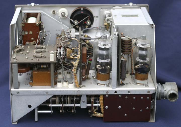
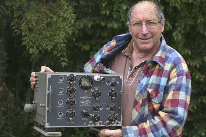
LATE 2007 - THE BENDIX TA12C A recent bout of shingles left me looking for a project that would take my mind of my poor condition. I selected my WW2 Bendix TA12C which I have been wanting to put on air for some years. I needed to make a 50W modulator, a power supply and some control circuitry and a cabinet to house these new units in. Well, I finished the project. The TA12C is now on air with 30W output and getting good reports. By the way, my shingles still continues after nearly 7 months! (as at 2nd Feb 2008)
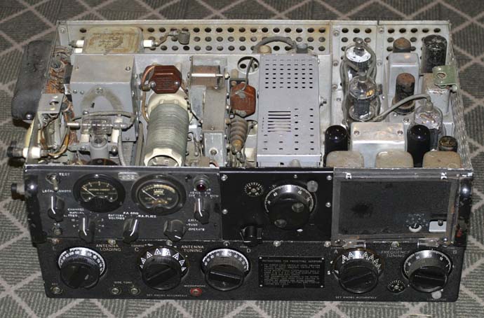
The TA12C
TA12C internals
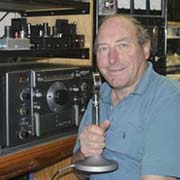
VK2BA and the TA12C
TA12C Modulator - 2 x 807's
TA12C equipment cabinet with the modulator fitted - the P/S is to go on the bottom and the top unit is control circuitry. It also needs a coat of paint. The old rig is now on air running about 30W o/p.
|
|
My PYE MTR1
I recently aquired this lovely PYE MTRI MK2 and matching receiver. This has been restored to the point where it has been on 40M and has made one on air QSO. Well, it does work! It is now in my museum.
|
![]()